
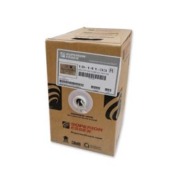
AMACO Telecom Outdoor Cable
APPLICATION
The cables are designed for use as subscriber distribution cables and as connection between central offices in local access networks. The cables are jelly filled and suitable for installation in ducts. The cables are also available for direct burial in the ground and aerial installation with integral suspension strand. An armored option is offered for direct burial installations.
Double Jacket, Jelly field, Armored, Unarmored can supply available upon request.
-
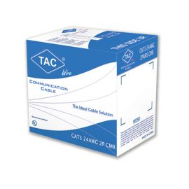
TAC CAT3 Indoor Telecom Cables
SAR146.00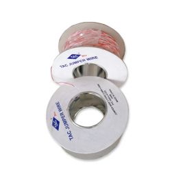
TAC Telecom Jumper Wire
SAR65.00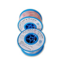
AMACO Telecom Jumper Wires
SAR87.00
CONSTRUCTION
General Spec.: Saudi Telecom Specification TS -2002 & IEC 60708
Conductor: Solid annealed plain copper wire as per ASTM B 3.
Insulation: Each Conductor shall be covered with continuous layer of Cellular Foam-Skin High Density Polyethylene. Insulation shall be identified as Table-1 & Table-2.
Assembly: Two Insulated conductors twisted together to form a pair. 10 Pairs are assembled to form a sub-unit. Up to 100 pairs, these sub-units are assembled to form the cable. For cables above 100 pairs, 5 and 10 sub-units are assembled to form a unit of 50 and 100 Pairs respectively. These units are stranded and filled with Petroleum Jelly filling compound to form the cable. The Final Assembly is covered with non-hygroscopic tape.
Moisture Barrier: Aluminum Tape, coated on both sides with co-polymer as per ASTM B 736, is applied longitudinally with a suitable overlap to prevent the ingress of water to the cable.
Sheath: Extruded black Linear Low Density Polyethylene, as per ASTM D 1248, continuously bonded to the aluminum tape to prevent of water penetration to the core and the transport of water between the sheath and the tape.
Electrical and Transmission Characteristics as per STC TS-2002
|
CHARACTERISTICS |
UNITS |
0.40 mm |
0.50 mm |
0.65 mm |
0.90 mm |
|
Conductor Resistance |
Ω/Km |
Max. 150 |
Max. 96 |
Max. 57 |
Max. 30 |
|
Resistance Unbalance |
% |
Max. 2.5 |
Max. 2.5 |
Max. 2.0 |
Max. 2.0 |
|
Insulation Resistance |
MΩ.KM |
Min. 2500 |
Min. 2500 |
Min. 2500 |
Min. 2500 |
|
Dielectric Strength |
|||||
|
Cond. - Cond. |
DC Volts |
2,400 |
2,400 |
3,000 |
3,600 |
|
Cond. - Shield |
DC Volts |
5,000 |
5,000 |
10,000 |
10,000 |
|
Mutual Capacitance |
nF/Km |
Max. 50.0 |
Max. 50.0 |
Max. 50.0 |
Max. 50.0 |
|
CUPP |
pF/500 M |
Max. 150 |
Max. 150 |
Max. 150 |
Max. 150 |
|
CUPG |
pF/Km |
Max. 2500 |
Max. 2500 |
Max. 2500 |
Max. 2500 |
|
Attenuation @ 1 KHz |
dB/Km |
Max. 1.81 |
Max. 1.45 |
Max. 1.10 |
Max. 0.80 |
|
Attenuation @ 1 MHz |
dB/Km |
Max. 25.7 |
Max. 21.00 |
Max. 16.30 |
Max. 13.6 |
|
PS NEXT @ 1KHz |
dB/Km |
Min. 70 |
Min. 70 |
Min. 70 |
Min. 70 |
|
PS NEXT @ 12KHz |
dB/Km |
Min. 67 |
Min. 67 |
Min. 67 |
Min. 67 |
|
PS NEXT @ 80KHz |
dB/Km |
Min. 55 |
Min. 55 |
Min. 55 |
Min. 55 |
|
PS NEXT @ 1000 KHz |
dB/Km |
Min. 37 |
Min. 37 |
Min. 37 |
Min. 37 |
|
PS ELFEXT @ 1KHz |
dB/Km |
Min. 74 |
Min. 74 |
Min. 74 |
Min. 74 |
|
PS ELFEXT @ 12KHz |
dB/Km |
Min. 71 |
Min. 71 |
Min. 71 |
Min. 71 |
|
PS ELFEXT @ 80KHz |
dB/Km |
Min. 58 |
Min. 58 |
Min. 58 |
Min. 58 |
|
PS ELFEXT @1000 KHz |
dB/Km |
Min. 36 |
Min. 36 |
Min. 36 |
Min. 36 |
Electrical and Transmission Characteristics as per IEC 60708
|
CHARACTERISTICS |
UNITS |
0.40 mm |
0.50 mm |
0.60 mm |
|
Conductor Resistance |
Ω/Km |
Max. 150 |
Max. 96 |
Max. 66.6 |
|
Resistance Unbalance |
% |
Max. 2.0 |
Max. 2.0 |
Max. 2.0 |
|
Insulation Resistance |
MΩ.KM |
Min. 1500 |
Min. 1500 |
Min. 1500 |
|
Dielectric Strength |
||||
|
Conductor - Conductor |
DC Volts for 3 S |
1,000 |
1,000 |
1,000 |
|
Conductor - Screen |
DC Volts for 3 S |
2,000 |
2,000 |
2,000 |
|
Mutual Capacitance |
nF/Km |
Max. 64.0 |
Max. 64.0 |
Max. 64.0 |
|
CUPP |
pF/500 M |
Max. 150 |
Max. 150 |
Max. 150 |
|
PS NEXT @ 150 KHz |
dB/Km |
Min. 49 |
Min. 49 |
Min. 49 |
|
PS NEXT @ 300 KHz |
dB/Km |
Min. 45 |
Min. 45 |
Min. 45 |
|
PS NEXT @ 1000 KHz |
dB/Km |
Min. 37 |
Min. 37 |
Min. 37 |
|
PS ELFEXT @ 150 KHz |
dB/Km |
Min. 54 |
Min. 54 |
Min. 54 |
|
PS ELFEXT @ 300 KHz |
dB/Km |
Min. 48 |
Min. 48 |
Min. 48 |
|
PS ELFEXT @ 1000 KHz |
dB/Km |
Min. 38 |
Min. 38 |
Min. 38 |